Split Ring Gearbox
May 2018
I thought of a way to produce extremely high gear ratios by using the fact that the velocity of a point close to where a spur gear and stationary internal gear mesh is near zero. By stacking a second spur gear on top of the first spur gear and making their pitch diameters almost (but not quite) the same, I can make this second spur gear drive a second internal gear at an extremely low speed. In this proof of concept, I have two stages of this gearbox, each with a gear ratio of 115:1. This results in an overall gear ratio of 13,225:1.
I later found out that Oskar van Deventer had already developed a more optimized design that produces a 1000:1 gear ratio per stage. Years later, I also learned about “split ring planetary gearboxes,” which have a different internal layout but use the same strategy of using two spur gears with almost the same pitch diameters. Interestingly enough, it seems like this gearbox design is not nearly as well-known as other “exotic” gearboxes like harmonic drives and cycloidal drives despite its ability to achieve a much higher gear ratio for a given bounding box and minimum tooth size. This strategy of using a small difference between the shapes of two components shows up in other mechanisms that produce extreme mechanical advantage such as differential screws and differential windlasses.


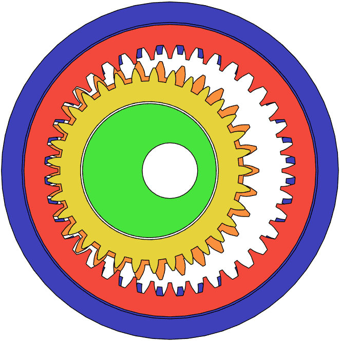
The gear ratio of the split ring gearbox may be calculated using the equation below. Note that the diameters refer only to pitch diameters, the blue gear is stationary, and the yellow and orange gears are joined together. The green component is the input and the red gear is the output.
R = Dorange Dred (Dblue - Dorange) (Dorange - Dyellow)
Alternatively, since the red gear’s pitch diameter is already fully determined by the pitch diameters of the other gears:
R = Dorange (Dblue - Dorange + Dyellow) (Dblue - Dorange) (Dorange - Dyellow)
Notice how the denominator has two terms that can be brought to near zero if the pitch diameters of certain gears almost match the pitch diameters of other gears. In fact, since all that matters is the pitch diameter, the gear module between the blue and orange gears can be different from the module between the yellow and red gears. This allows the orange and yellow gears to have more similar pitch diameters than they would if they were forced to have the same module. With some optimization, a single stage that only uses gears with around 40 teeth each (especially if they use a flatter tooth geometry like in Oskar van Deventer’s design) could surpass a 1000:1 gear ratio.
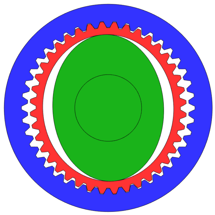
As for the harmonic drive, its gear ratio may be calculated using the equation below. I use number of teeth instead of pitch diameter here because of the red flex spline. Also note that the blue gear is stationary, the green component is the input, and the red flex spline is the output.
R = − Nred Nblue - Nred
Since the denominator cannot be less than 1, the maximum gear ratio of a harmonic drive is the number of teeth on the flex spline. This means that if the gears had around 40 teeth each, the gear ratio would be capped at 40:1, which is 1/25th of the 1000:1 gear ratio of a split ring gearbox that also had around 40 teeth per gear. The same analysis on gear ratio holds for cycloidal drives, which have a very similar gear ratio formula as harmonic drives.
In July 2018, I continued to explore this gearbox design by designing a -1:1 coaxial gearbox. Gearboxes that coaxially reverse the directions of their shafts are notable because they can also be used as differentials by rotating the case of the gearbox instead of one of the shafts. This design only uses one intermediate moving component (green) and its construction out of layered 2D shapes could make it easier to manufacture compared to something like bevel gears. The layered 2D structure of the gearbox and the fact that the geometries nest within each other could also make this design unusually compact, especially in the axial direction.