RGB Exit Light
May - Jun 2024
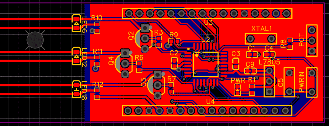
One day, my friend moved out of town and donated a lot of his things. Among the things he donated was an exit light. I held onto it for a while, and eventually I thought it would be fun to develop my PCB skills by making it flash through random RGB colors instead of glowing with a constant, boring red light. Since the function was relatively simple and I was using an Arduino, the challenge was not with designing the schematic or the Arduino code. Rather, the challenge was learning how to use ECAD software (EasyEDA in this case) and how to use a standalone Arduino chip (ATmega328P with a TQFP footprint) instead of an Arduino board.
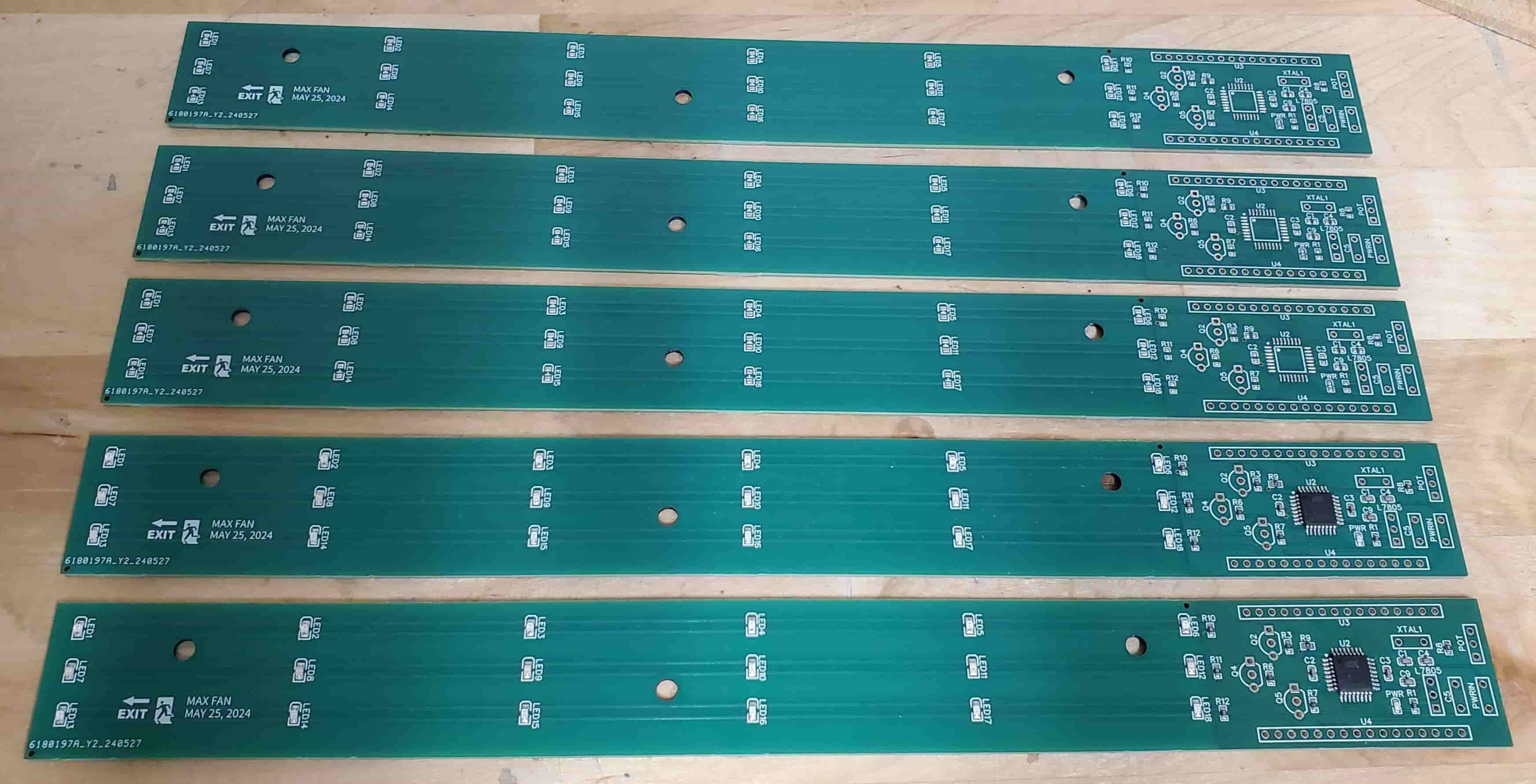
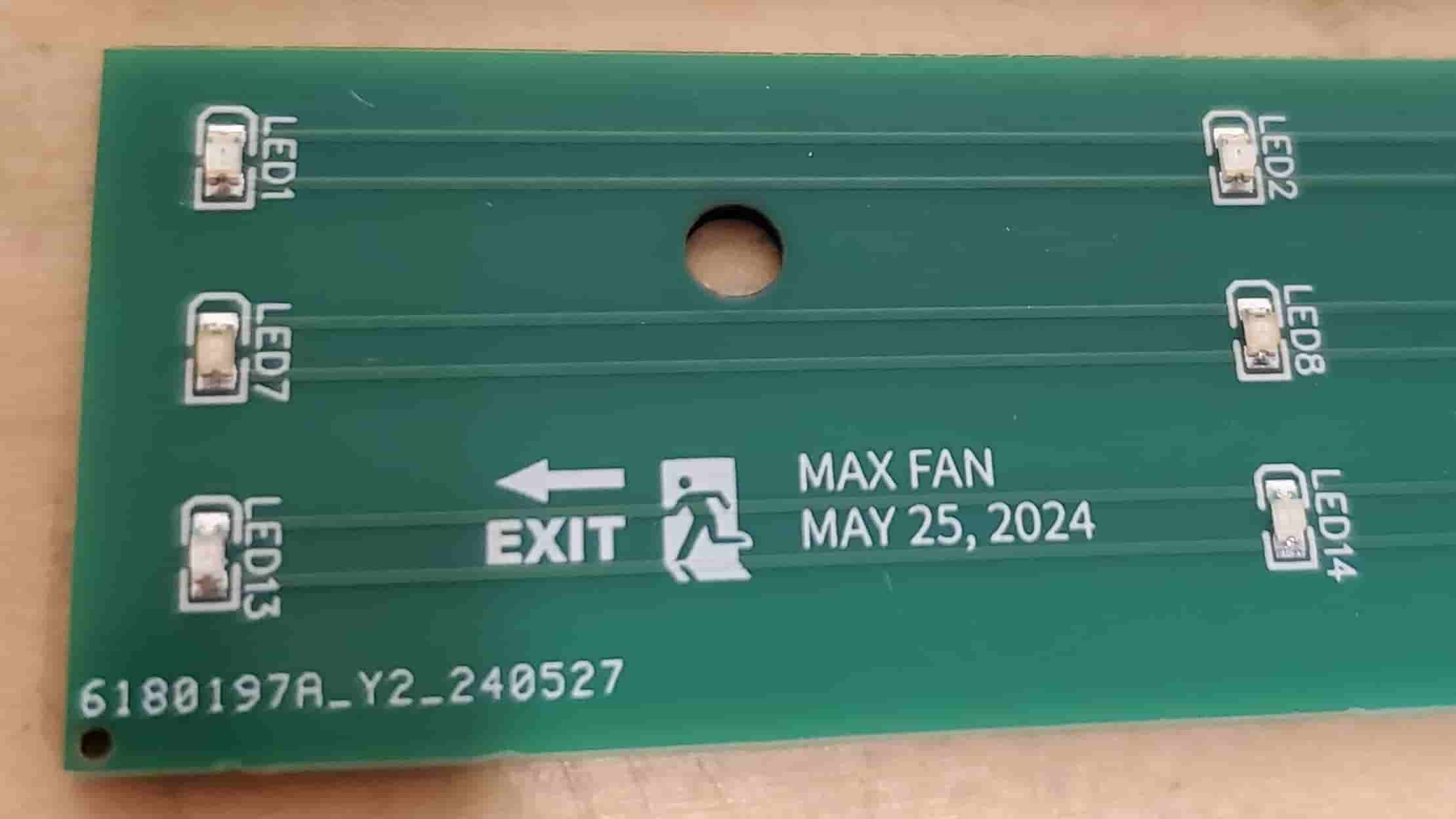
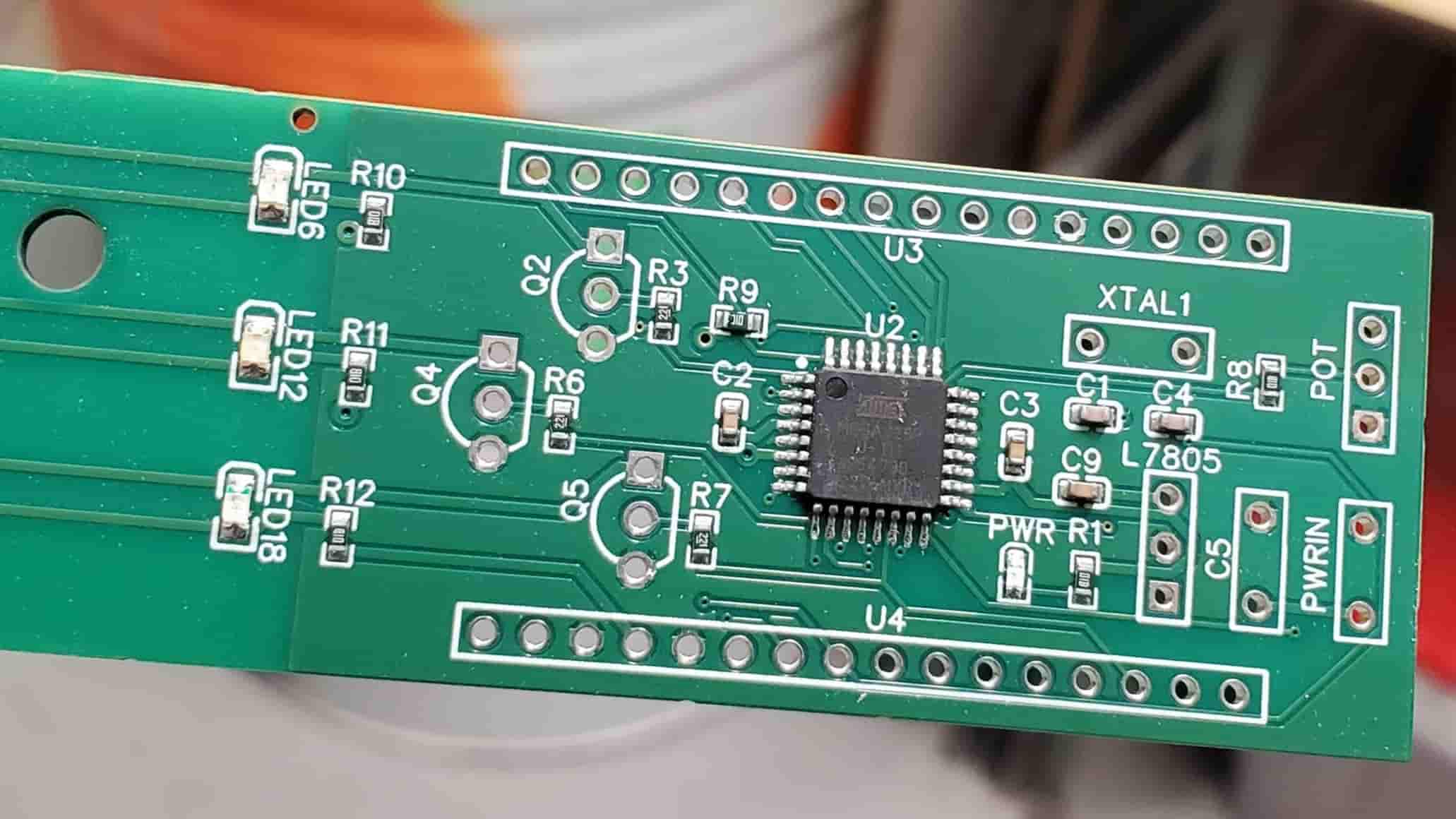
After I finished making the PCB in EasyEDA, I ordered the boards from JLCPCB. I had JLCPCB assemble some of these boards with all their SMD components. When assembling boards with JLCPCB, it’s worth noting that JLCPCB has “basic” and “extended” parts. Basic parts are common parts (e.g., resistors and capacitors) that are already on their pick and place machines whereas extended parts are parts that have to be manually loaded onto their machines. They charge $3 for each unique extended part.
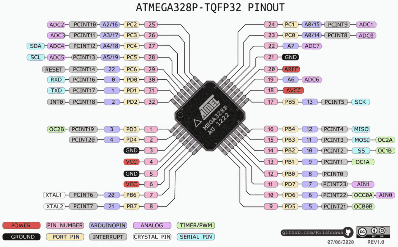
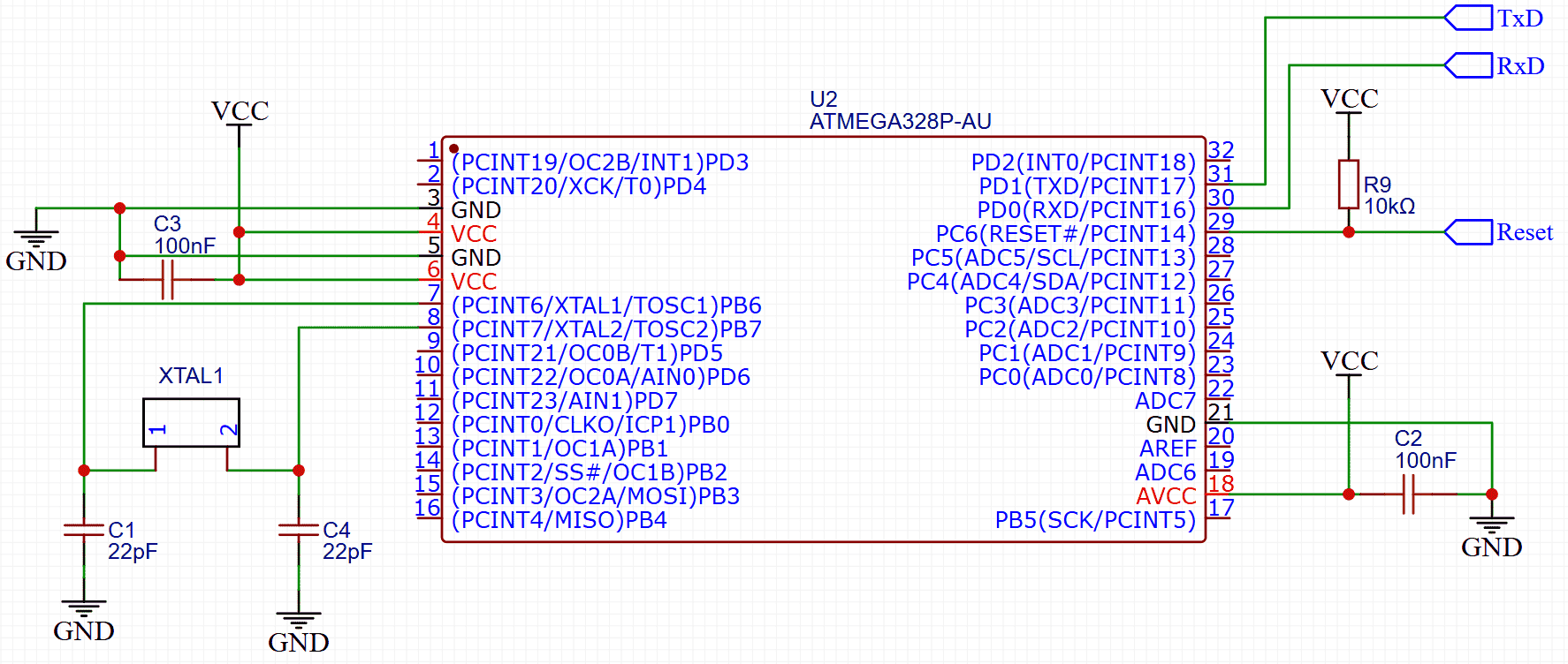
In order to use the ATmega328P chip on my board, I needed to first include some peripherals and burn the bootloader onto the chip. I used GreatScott’s video to figure out where to attach peripherals like a 16 MHz crystal oscillator (pin numbers 7 and 8), two 22 pF capacitors (pin number 7, 8), and a 10k pullup resistor (pin number 29) as well as which pins should be connected to VCC (pin numbers 4, 6, and 18) and ground (pin numbers 5 and 21). The exact connections I used are shown in my schematic above.
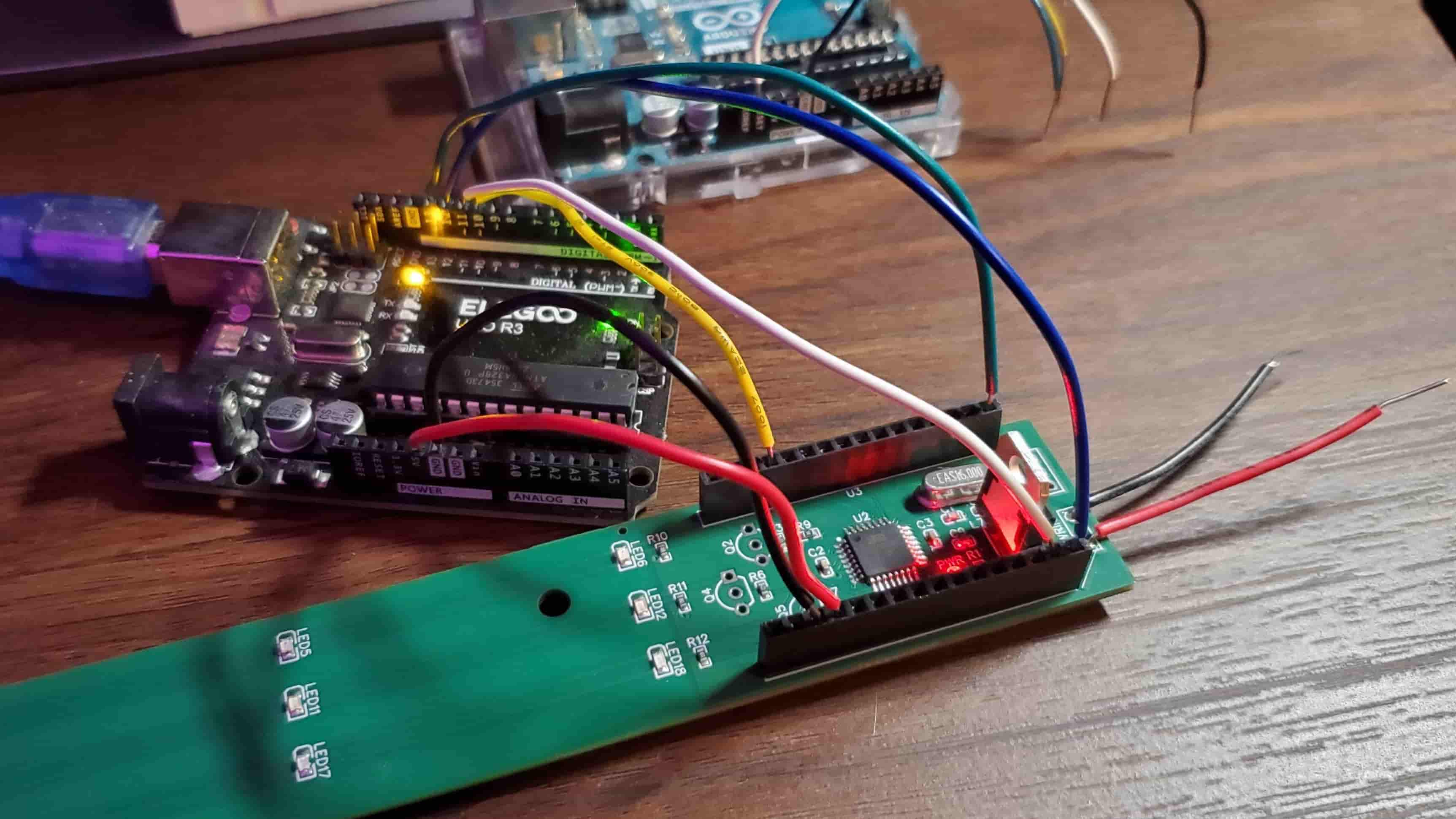
Since the ATmega328P did not come with a bootloader, I burned the bootloader onto the chip using this Arduino guide and a spare Arduino Uno. Specifically, I connected Arduino pin 10 of the Uno to the chip’s reset (pin number 29) and Arduino pins 11, 12, and 13 of the Uno (corresponding to COPI, CIPO, and SCK) to the chip’s pin numbers 15, 16, and 17. I then connected the Uno’s 5V and ground connections to the 5V and ground connections of the chip and proceeded with burning the bootloader using the Arduino IDE. To make connecting the pins of the Uno to the pins of the chip as easy as possible, on my PCB I added female header pins and made sure to keep them in the same order as the chip’s pin numbers in my schematic.
To upload my sketch to the chip, I once again used GreatScott’s video as a guide. Since the chip of my spare Arduino Uno was in a removable DIP package, I removed the Uno’s chip and connected the Uno board’s TX, RX, reset, and ground pins to the corresponding pins on the PCB chip (pin numbers 29, 30, 31, and 3) and uploaded my sketch.
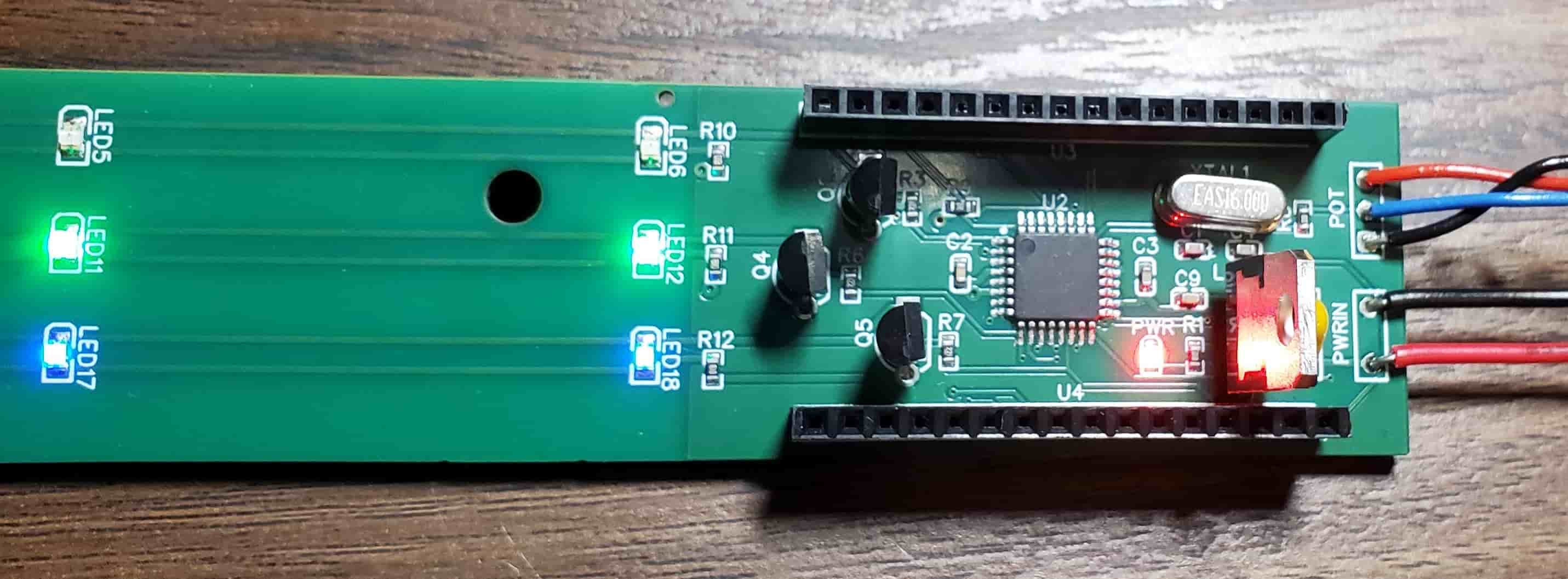
After uploading my sketch, the Arduino worked as intended. I made some tweaks to the hardware by adding a translucent acrylic panel to the front (for diffusing light), adding a mirror to the back (to increase the brightness of the front), and soldering in brighter LEDs, and then it was done. In addition to giving me experience with ECAD and using Arduino chips in PCBs, it had the unexpected benefit of serving as a nice night light for my room.