Reverse Engineering a Bluebike
Feb - Mar 2025
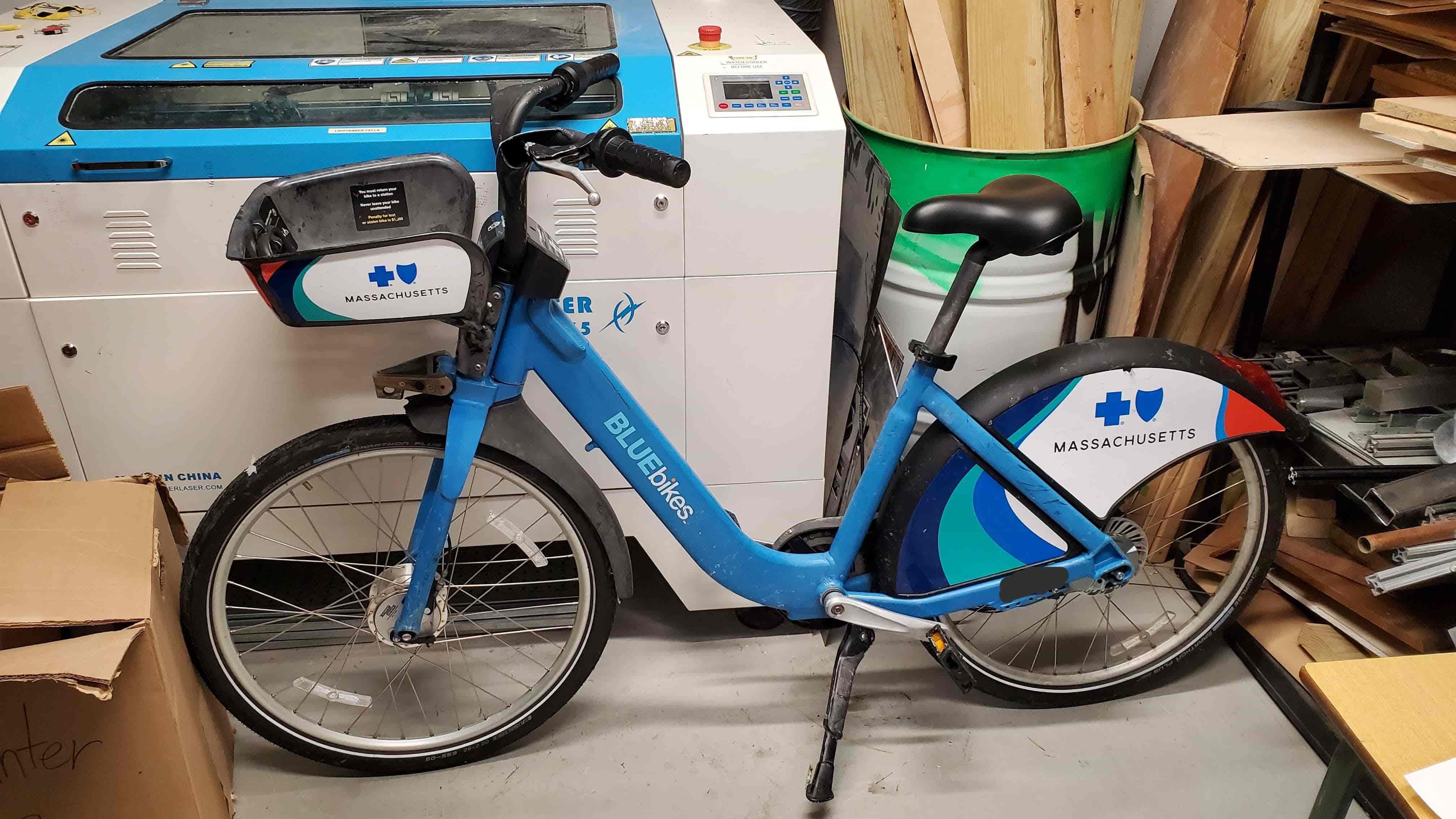
Bluebikes is a bicycle sharing service in Boston. To use one, you go to a dock, rent a bike for around $3, and then put it back at any dock in the city once you’re done. One day, I noticed a Bluebike left discarded on the side of the street. When I came back 12 hours later and noticed that it was still there, I concluded that it was abandoned and decided to learn as much as I could from it. I was curious about everything ranging from its electronics to its brakes, but I was particularly curious about the gear shifter. Unlike most bikes which only allow you to switch between discrete gear ratios, Bluebikes allow you to switch continuously between gear ratios.
Electronics
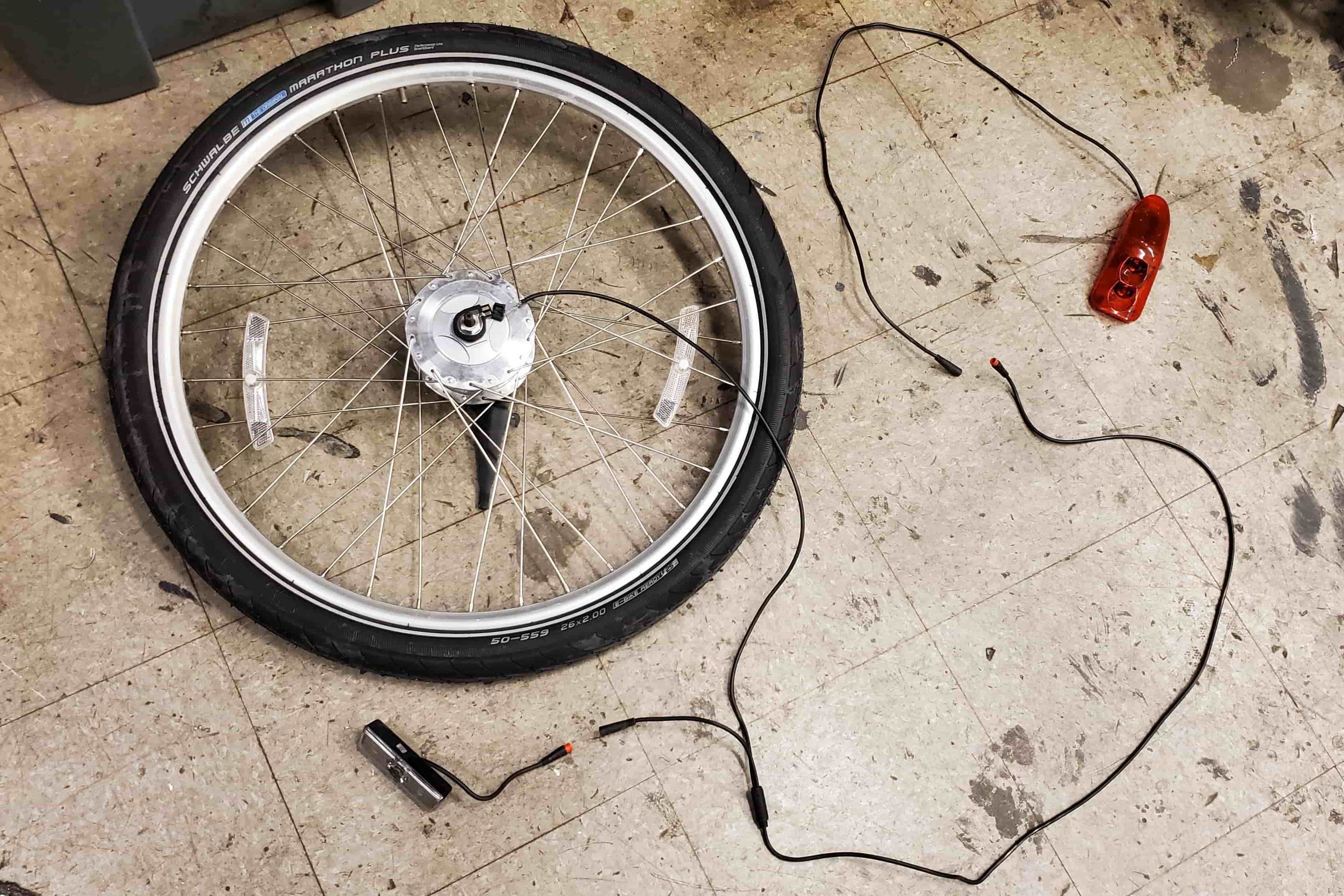
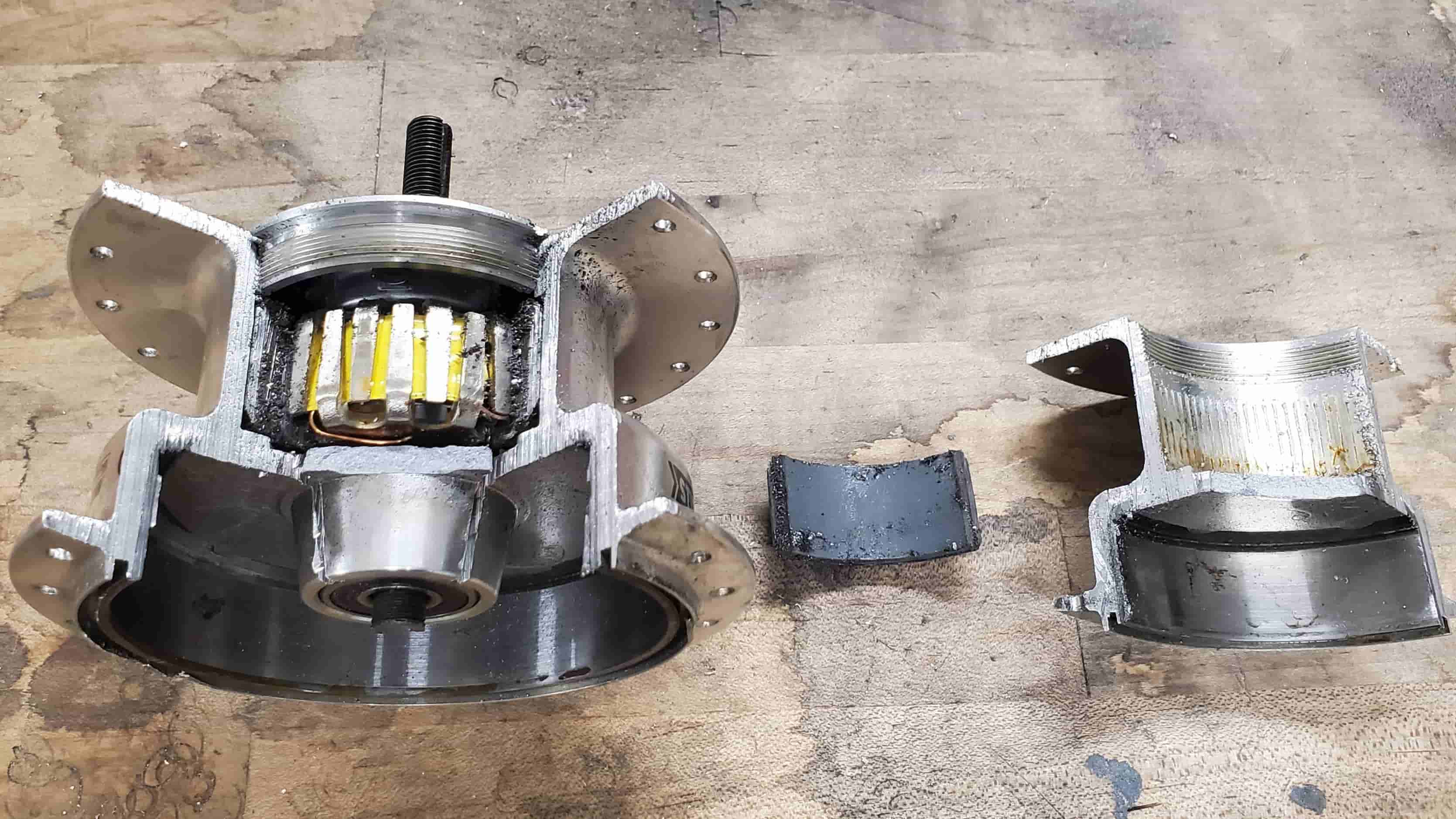
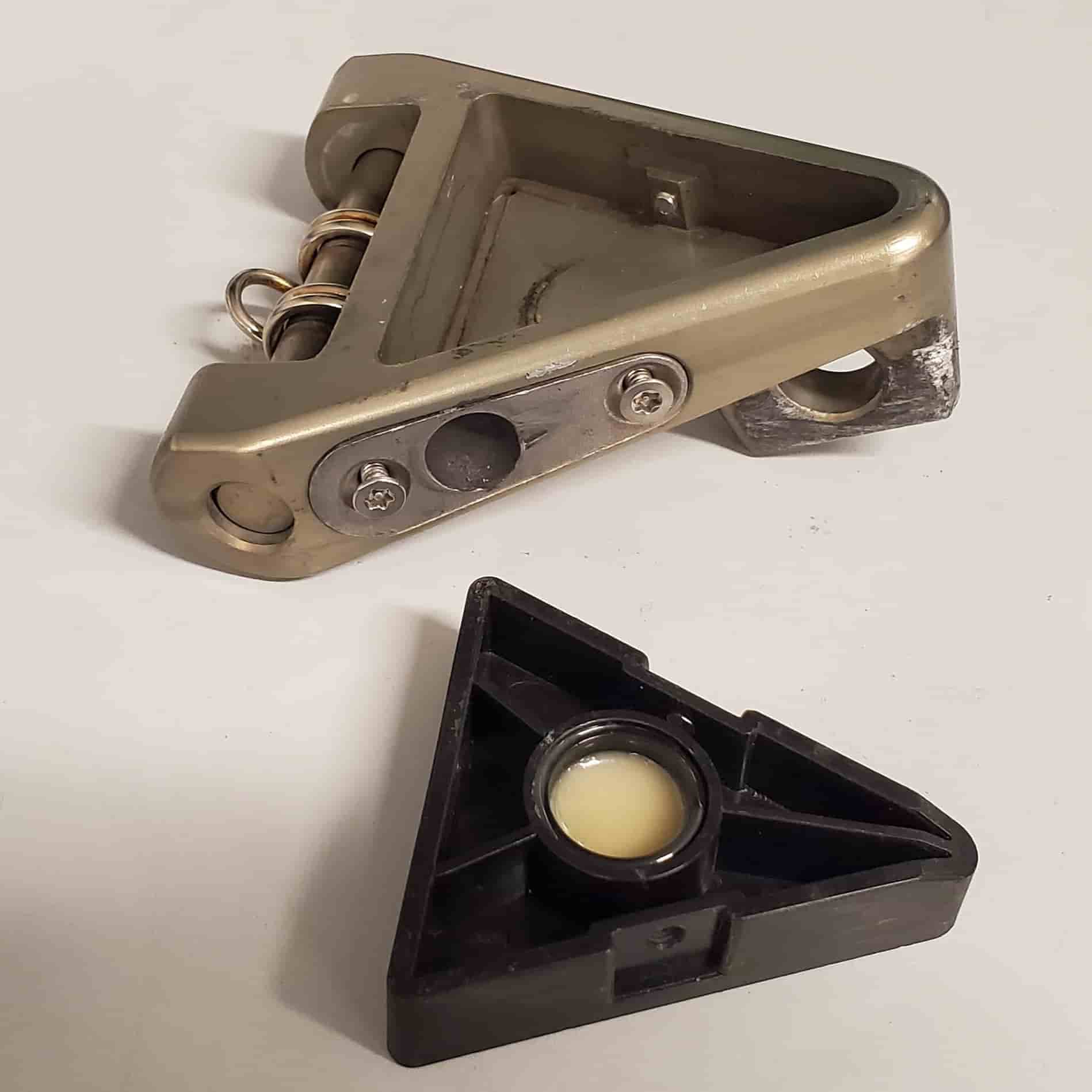
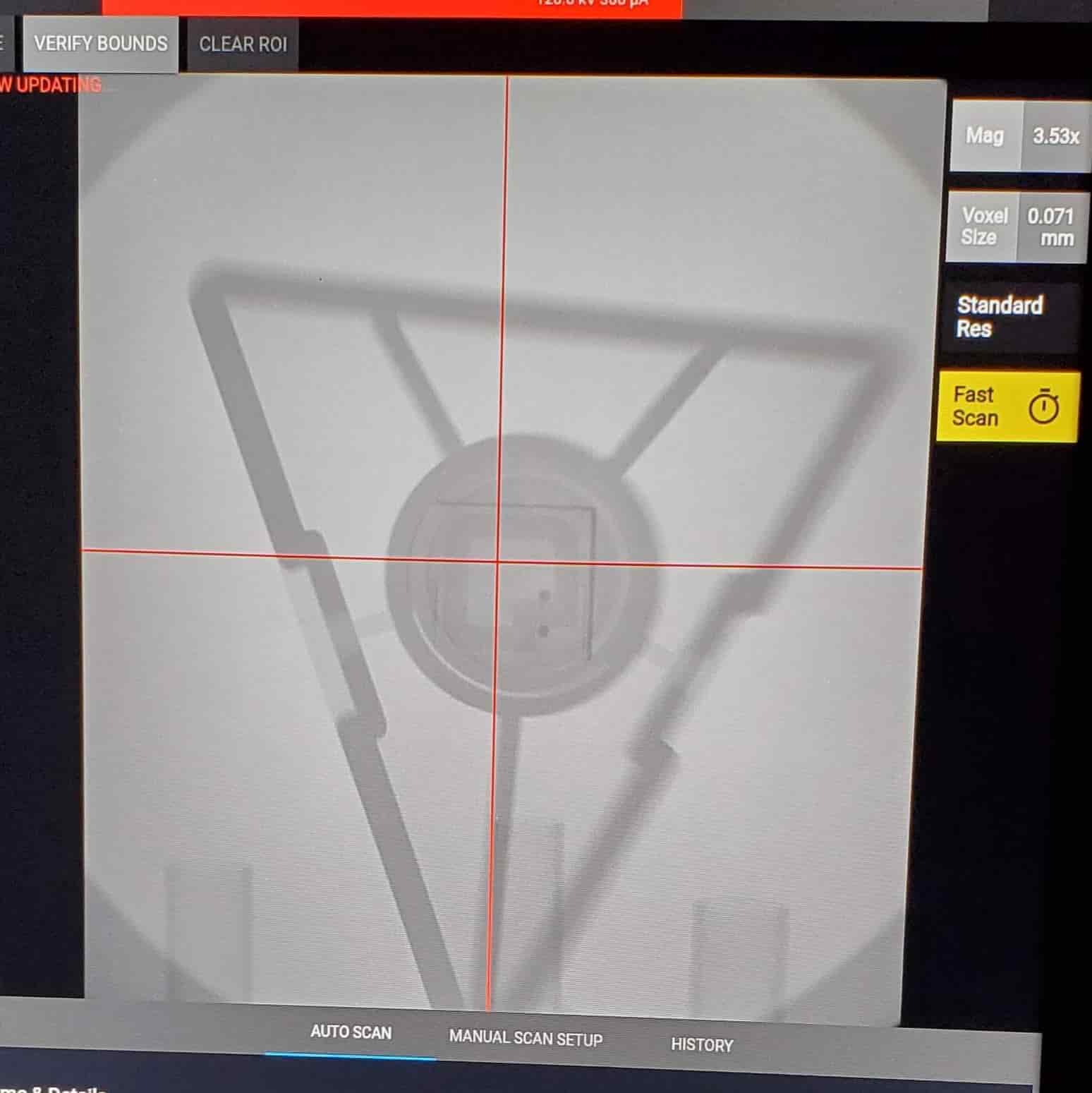
The electronics are surprisingly simple. The front wheel hub houses a generator that powers the front and rear lights, and the docking triangle contains an RFID chip potted inside (which I saw using an X ray scanner). There is no tracking device in the bike.
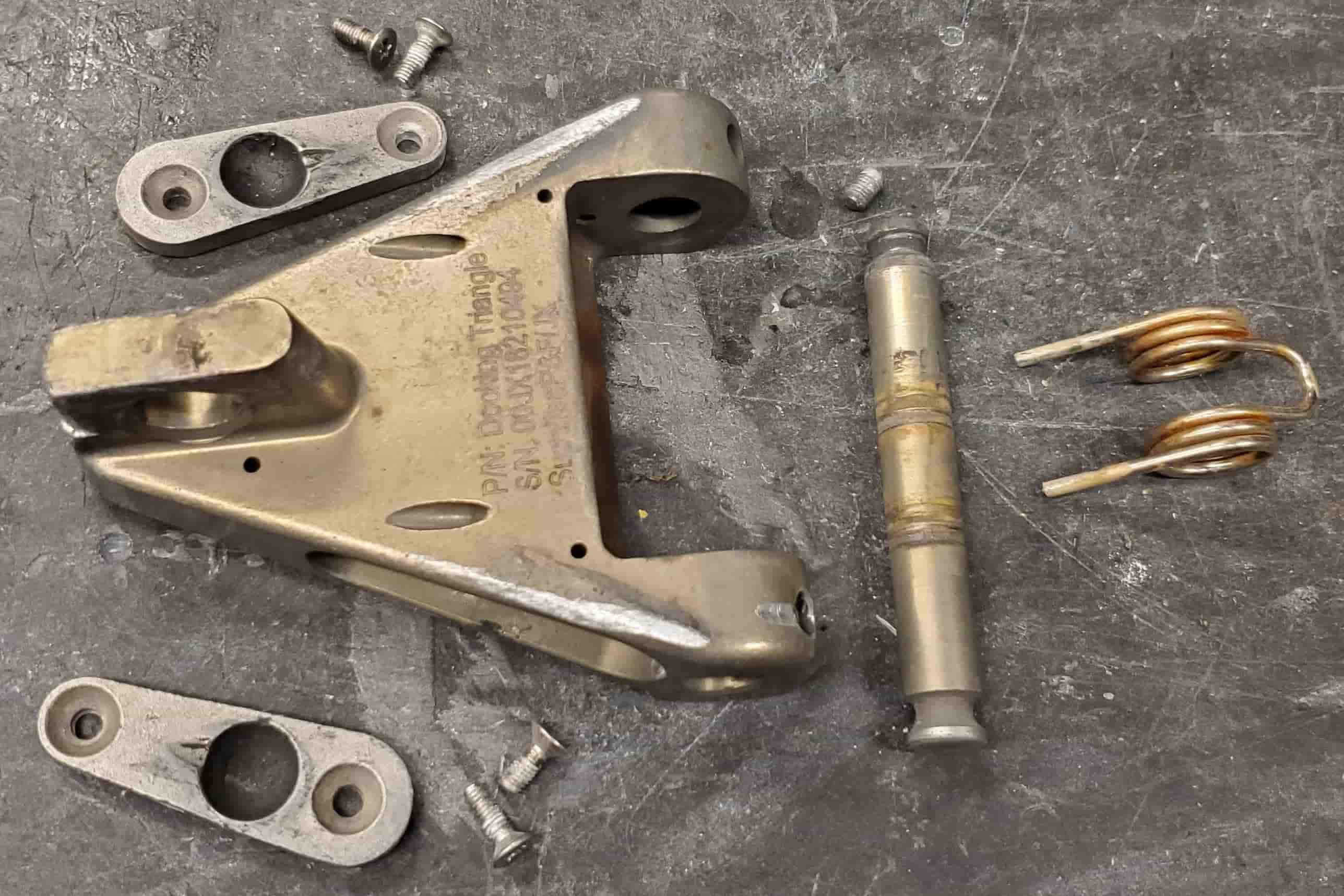
The docking triangle axle is fastened using set screws, which means one could remove it relatively easily. If the docking triangle is placed into the Bluebike docking station without the rest of the bike, the docking station likely wouldn’t be able to tell that the rest of the bike isn’t attached.
Structure
Even though the bike is quite heavy, the frame is aluminum, not steel. Around half the weight of the bike is due to the frame, and the other half are the two wheels. All the fasteners are metric.
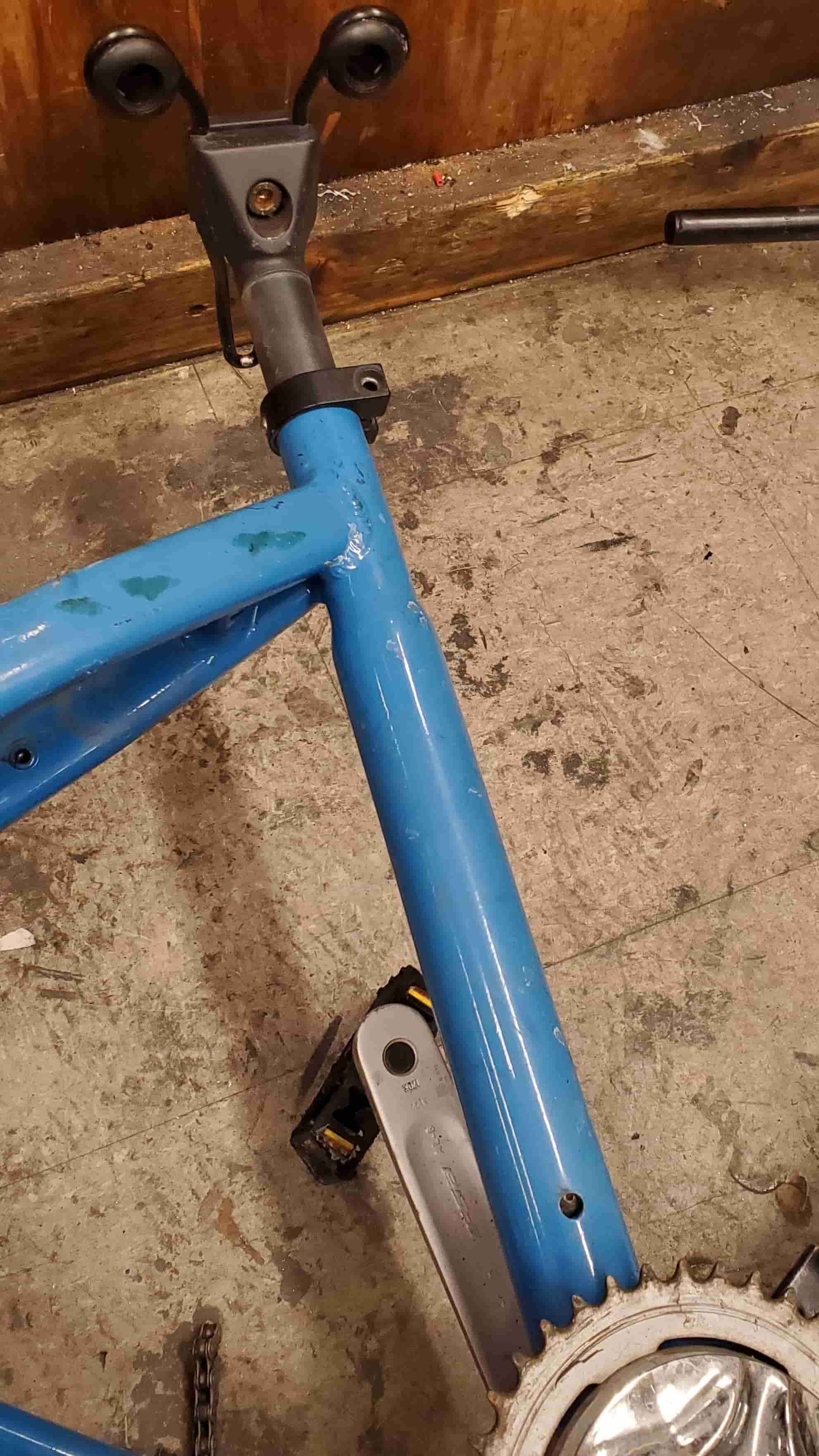
A side screw prevents the seat post from being pulled out of the bike. You have to rotate the seat 90 degrees counterclockwise and then unscrew the screw through a small hole on the right side of the frame.
Gear Shifter
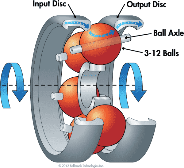
The working principle is illustrated by this image. The change in the steel ball’s axis of rotation changes the gear ratio because the gear ratio is the ratio of the distance covered by the contact point between the ball and input disk over one rotation of the ball to the distance covered by the contact point between the ball and output disk over that same rotation. Just like how the circumference of a circle on Earth at one latitude does not equal the circumference of a circle at another latitude, tilting the ball axis will change those latitudes and therefore the gear ratio.
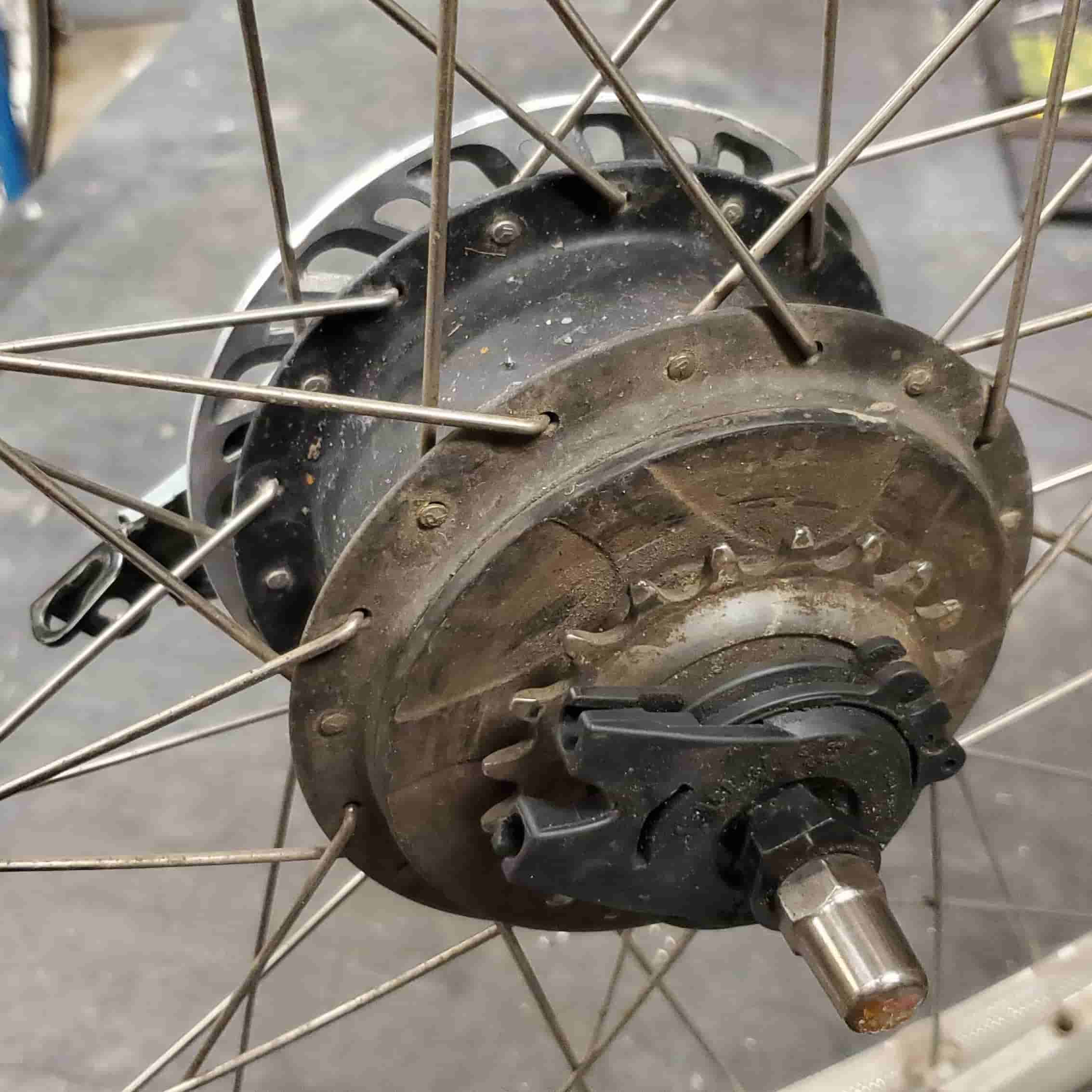
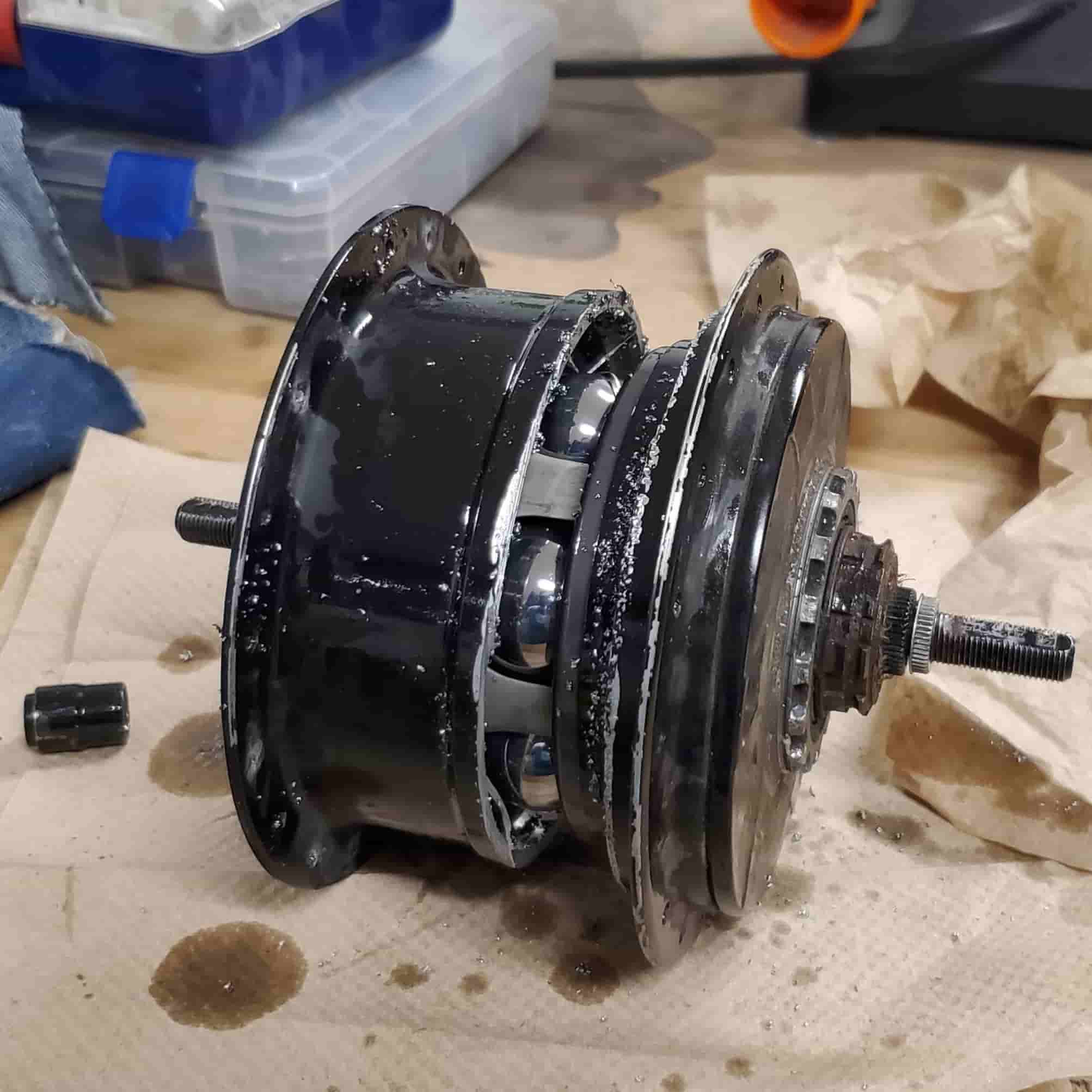
The back wheel hub contains the continuously variable gear shifter. It was made by Enviolo. Enviolo has a nice animation showing how the device works. In the second picture, I removed the sprocket and gear ratio adjuster. They would be mounted on the right side of the picture.
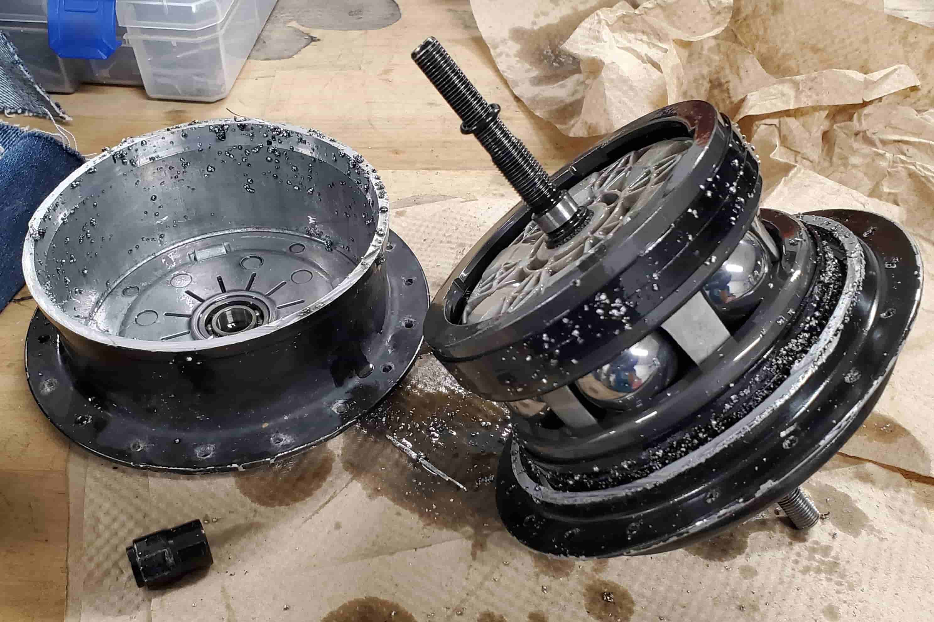
The sprocket directly drives the gray disk to the right of the large steel balls. The rotation of this gray disk causes the steel balls to rotate with it. The axis of rotation of each steel ball can be adjusted so that it isn’t parallel with the hub axis. This is what permits a continuously variable gear ratio as shown in the very first diagram. The hub contains a large amount of low viscosity gray-colored fluid, which I had mostly drained out before disassembly. According to the manufacturer Enviolo, this fluid thickens under the high pressure between the gray disk and the balls. This prevents the disk and balls from slipping under load. The balls drive another gray disk to their left.
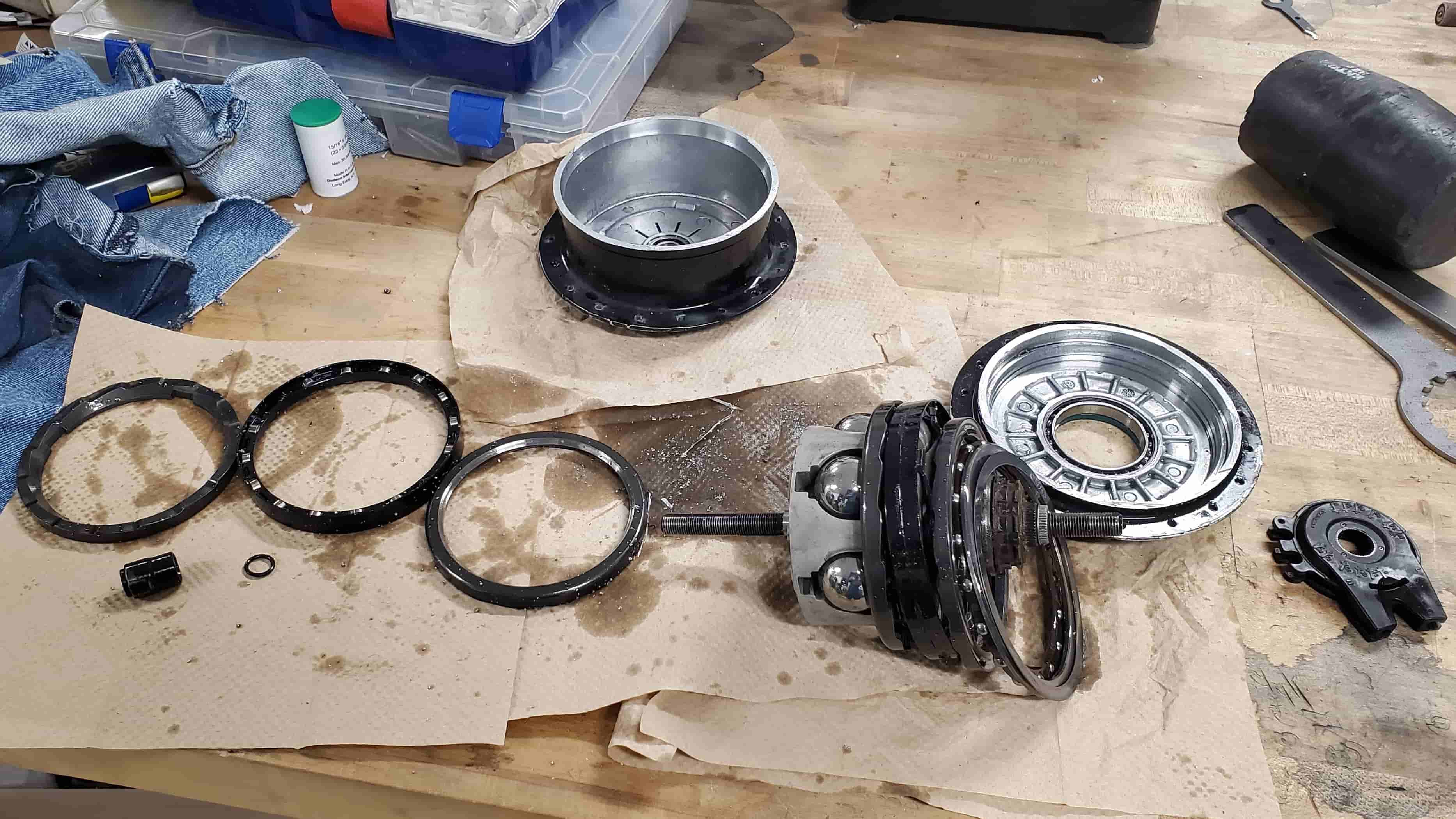
The gray disks are sandwiched next to other disks that contain rollers and camming surfaces. When clockwise torque is applied through the sprocket, these components try to spread out but are constrained by the axial width of the hub. This forces the gray disks to push tightly against the large steel balls in the middle, which helps prevent slippage.
The disk to the far left has rectangular cutouts that engage with the hub housing. Since the spokes of the wheel are mounted to the hub housing, the entire back wheel moves with that far left disk. To the far right, you can see a thrust bearing that prevents the components on the right from rubbing against the hub housing. This is necessary because the sprocket rotational speed won’t necessarily match the wheel rotational speed due to the adjustable gear ratio.
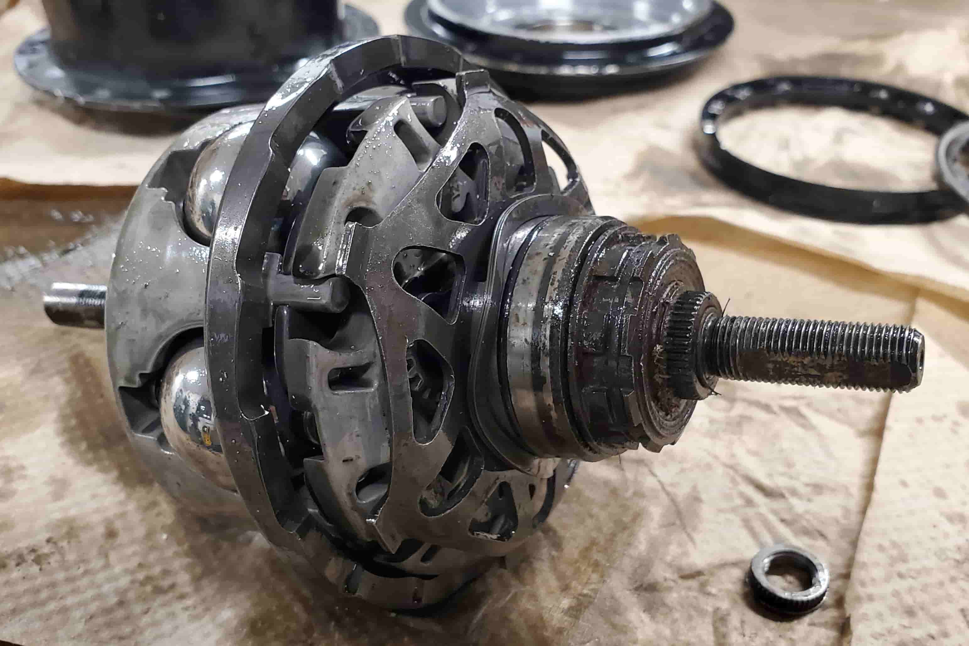
The sprocket goes on the brown component to the right that has rectangular cutouts in it. The gear ratio adjuster goes onto the smaller black component even further to the right that has splines cut into it. Also note the wave spring, which ensures there is always preload between the disks and the steel balls.
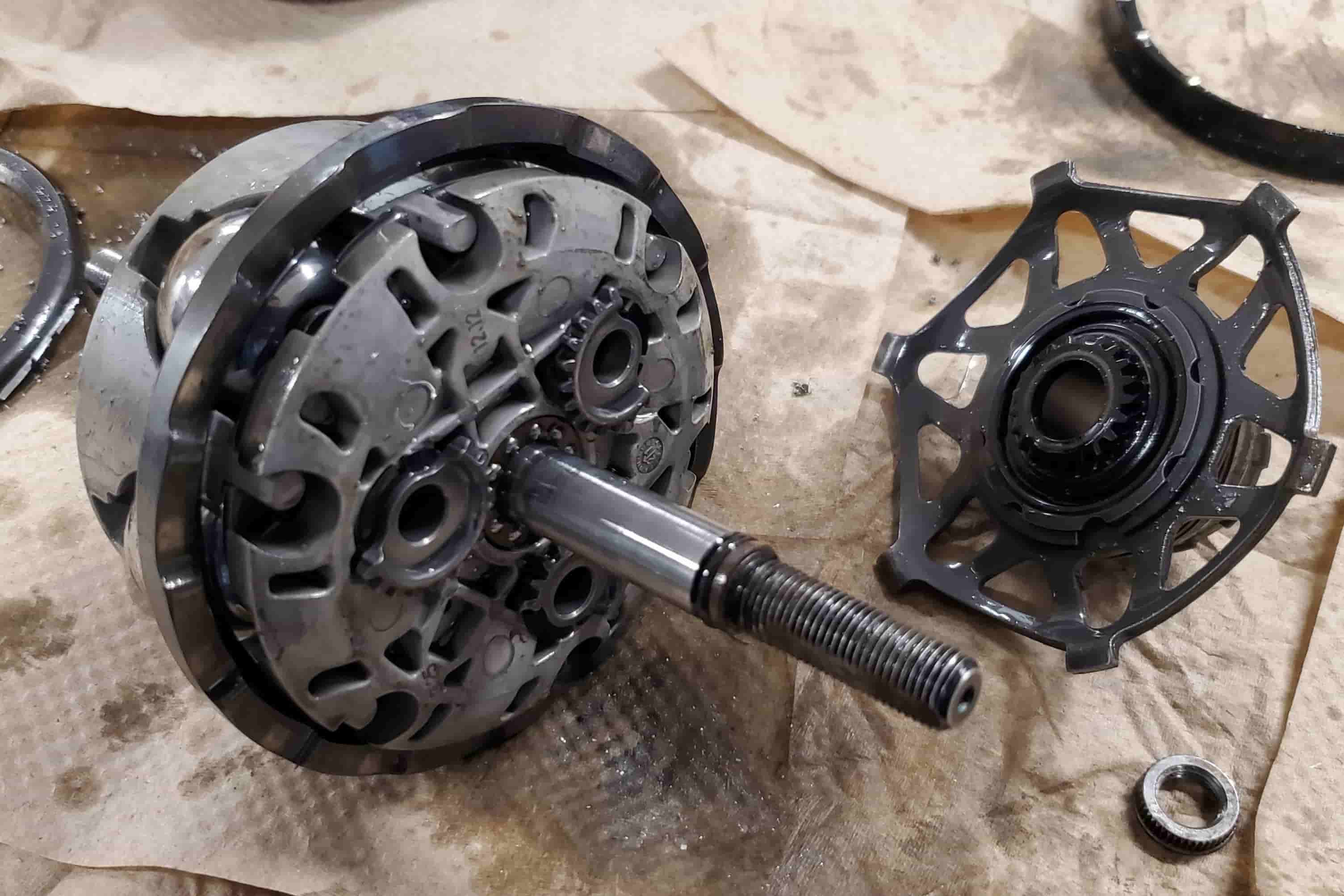
The gear ratio adjuster is connected to the black gear to the right. Rotating it causes the three partial planetary gears to also rotate.
The hexagonal sheet metal part to the right that contains 6 rectangular protrusions is connected to the sprocket. It allows the rotation of the sprocket to drive the rotation of the gray disk to the right of the large steel balls.
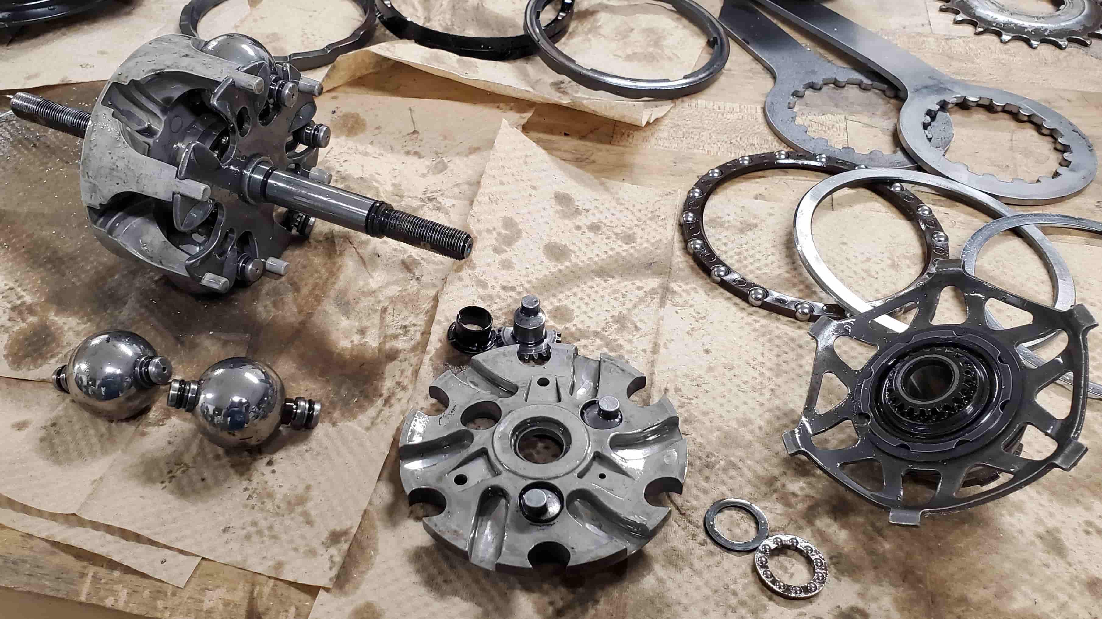
Here, you can see the underside of the planetary gears, housed inside of a gray plate (bottom center). When these gears rotate, their off-centered circular bosses cause the entire gray plate in which they are housed to rotate. The slots in this gray plate then cam one end of the axles of the steel balls radially inward or outward. Due to the shape of the gray ball housing (top left), the other end of the axles will move radially in the opposite direction. Note that the gray ball housing is fixed to the hub shaft, and this shaft is fixed to the bike frame so that it doesn’t rotate. This ensures that when the gray plate rotates, it doesn’t just drag the gray ball housing with it. As a result, the steel ball center position remains the same but its axis of rotation changes. As noted in the very first diagram, the ability to adjust the axis of rotation of the steel balls is what allows this gear shifter to achieve a continuous range of gear ratios.
Brakes
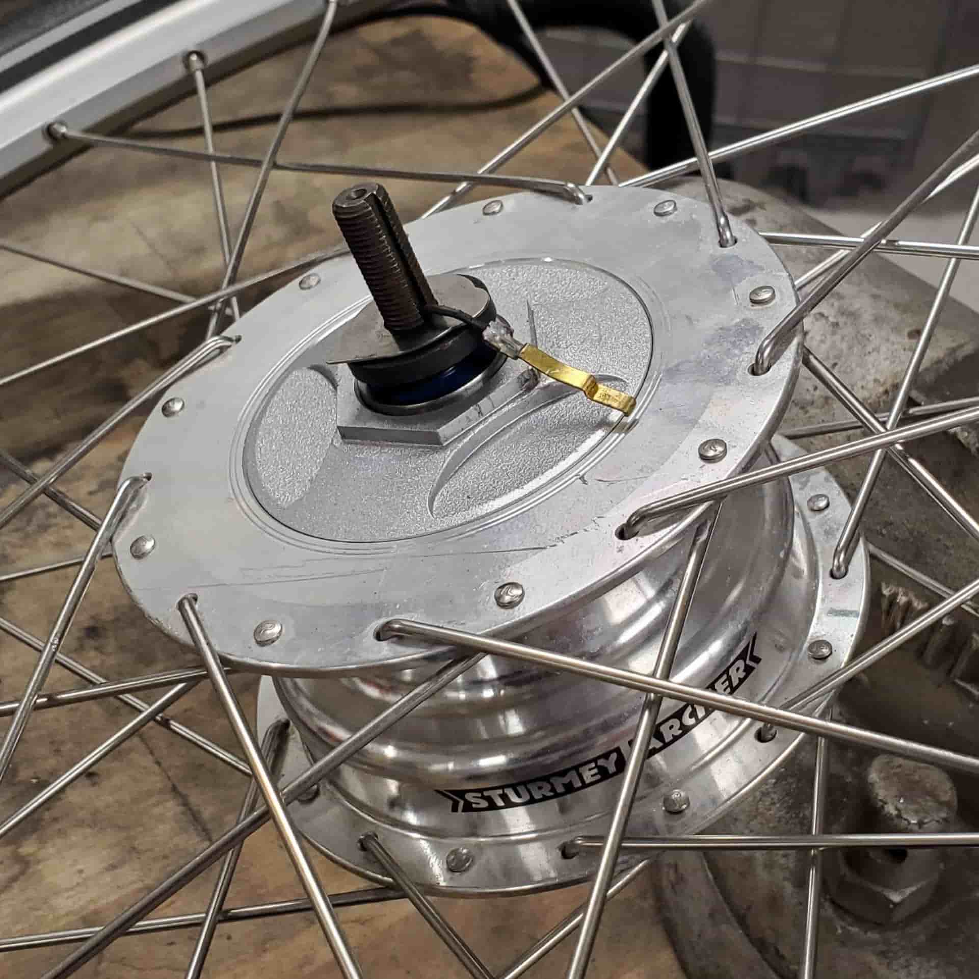
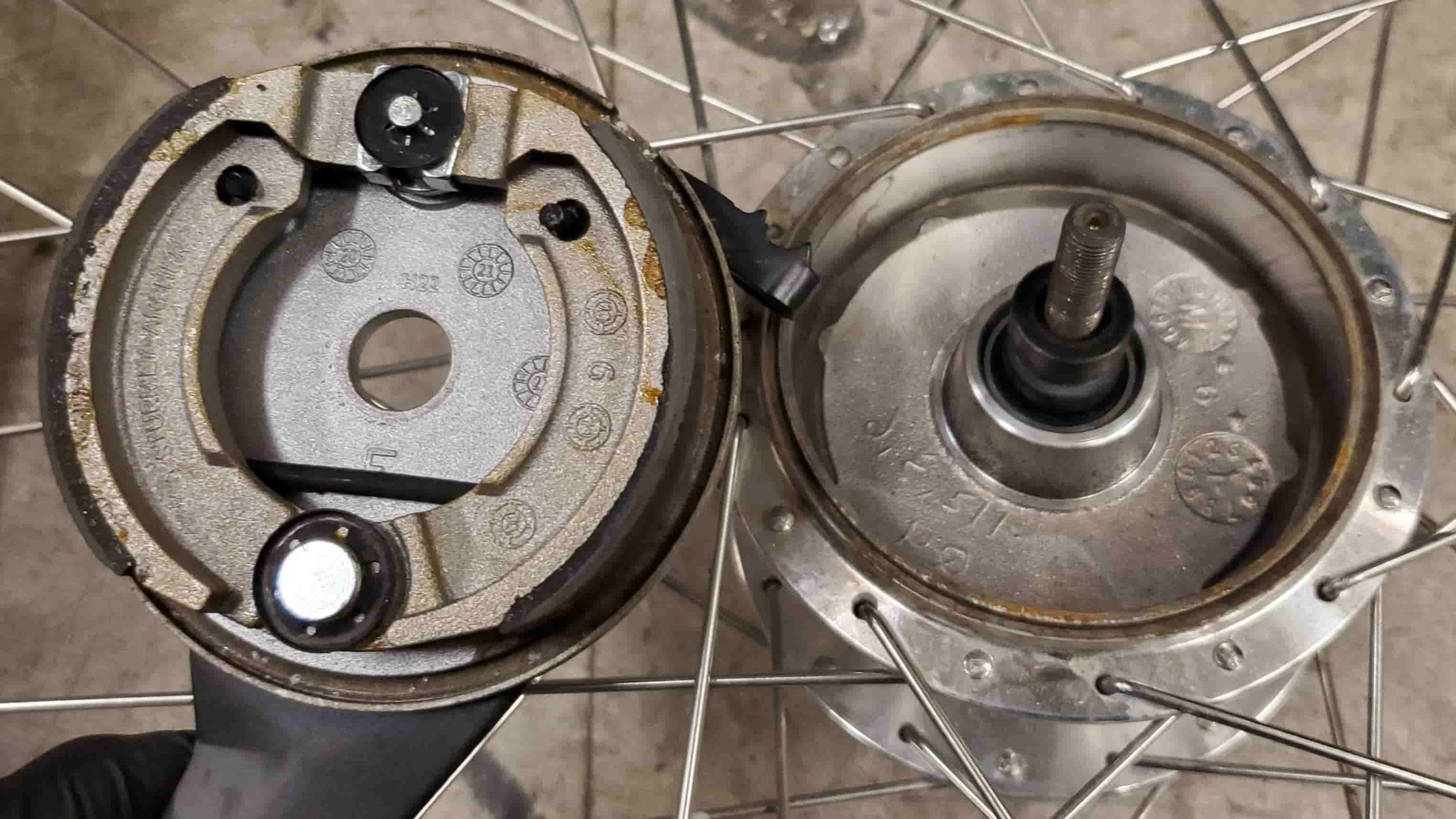
The front brake is a Sturmey Archer XL-FDD. It contains a drum brake on one side and the generator that powers the electronics on the other side (picture in the electronics section). Bluebike probably used this brake because unlike the more common disk or caliper brakes, this one is fully enclosed and protected from weather/vandalism.
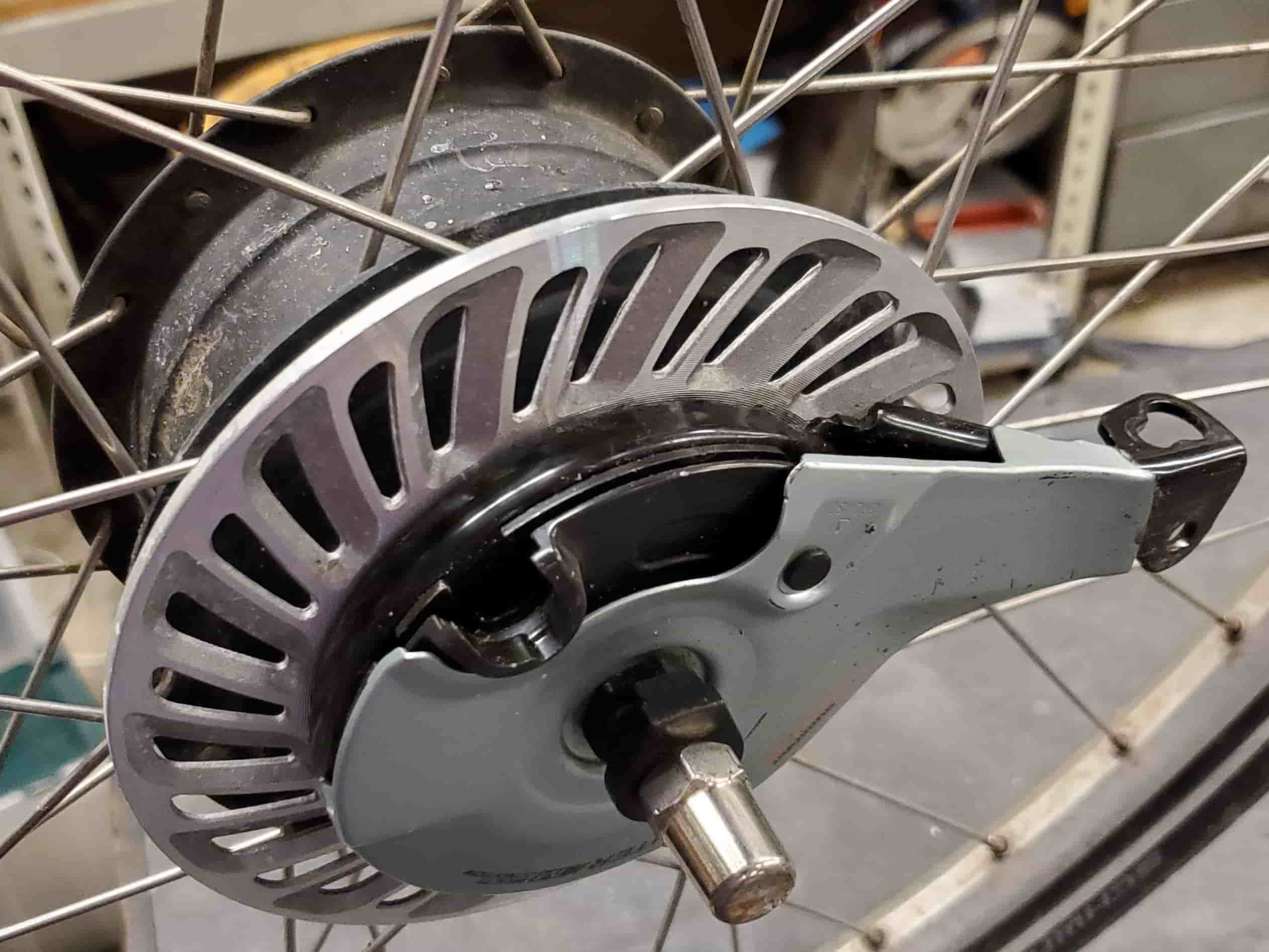
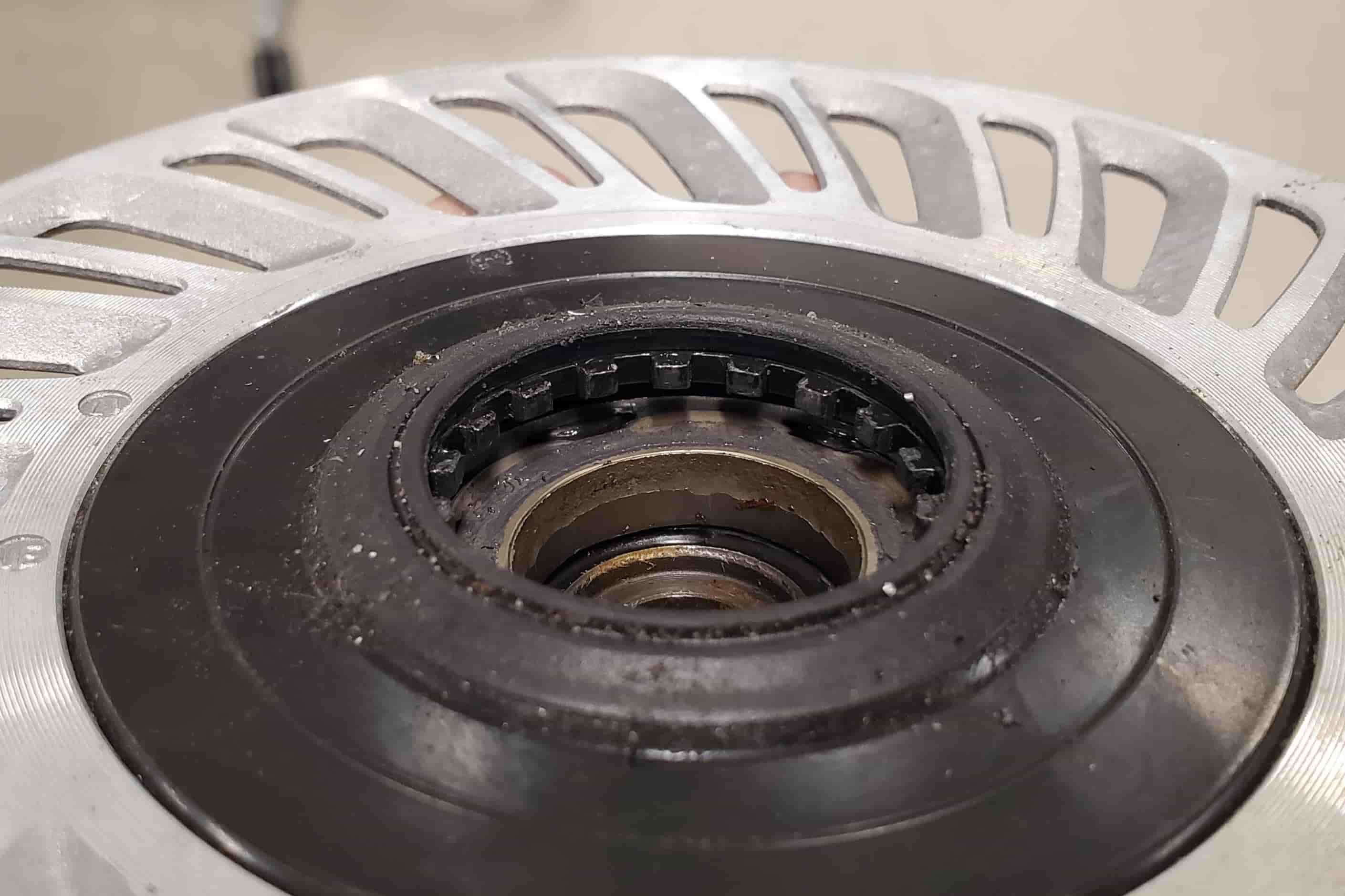
The back brake is a Shimano Nexus roller brake. The splined component rotates with the back wheel. The metal disk below that is the brake actuator. When that metal disk is rotated, it cams cylindrical rollers (barely visible in the photo) outward and causes the splined component (and therefore the wheel) to lock up with the rest of the brake, which is fixed against the frame of the bike. Bluebike probably used this exotic brake because its flat compactness gave more room for the bulky continuously variable gear shifter housed in the rest of the hub and the functional parts of this brake are well-protected from weather/vandalism. (I’m assuming the big, exposed aluminum disk with holes in it is there to provide cooling to the brake).
Other
The Bluebike likely feels inefficient due to the high weight, the limited gear ratio at its highest gear, the inefficiency of the front wheel’s electric generator, and the viscous losses inside the back wheel’s gear shifting hub.
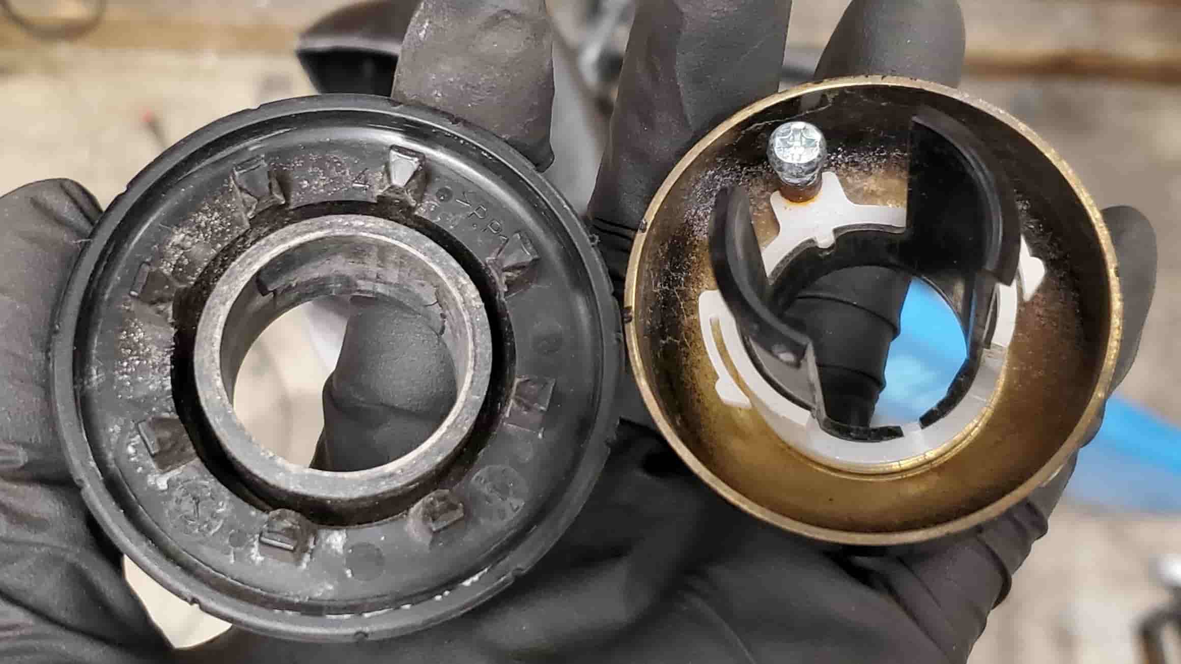
When you twist the black plastic piece on the bell, it cams a screw that’s attached to a spring radially inward. Once you’ve twisted the black plastic piece enough, the screw snaps radially outward and strikes the metal bell.
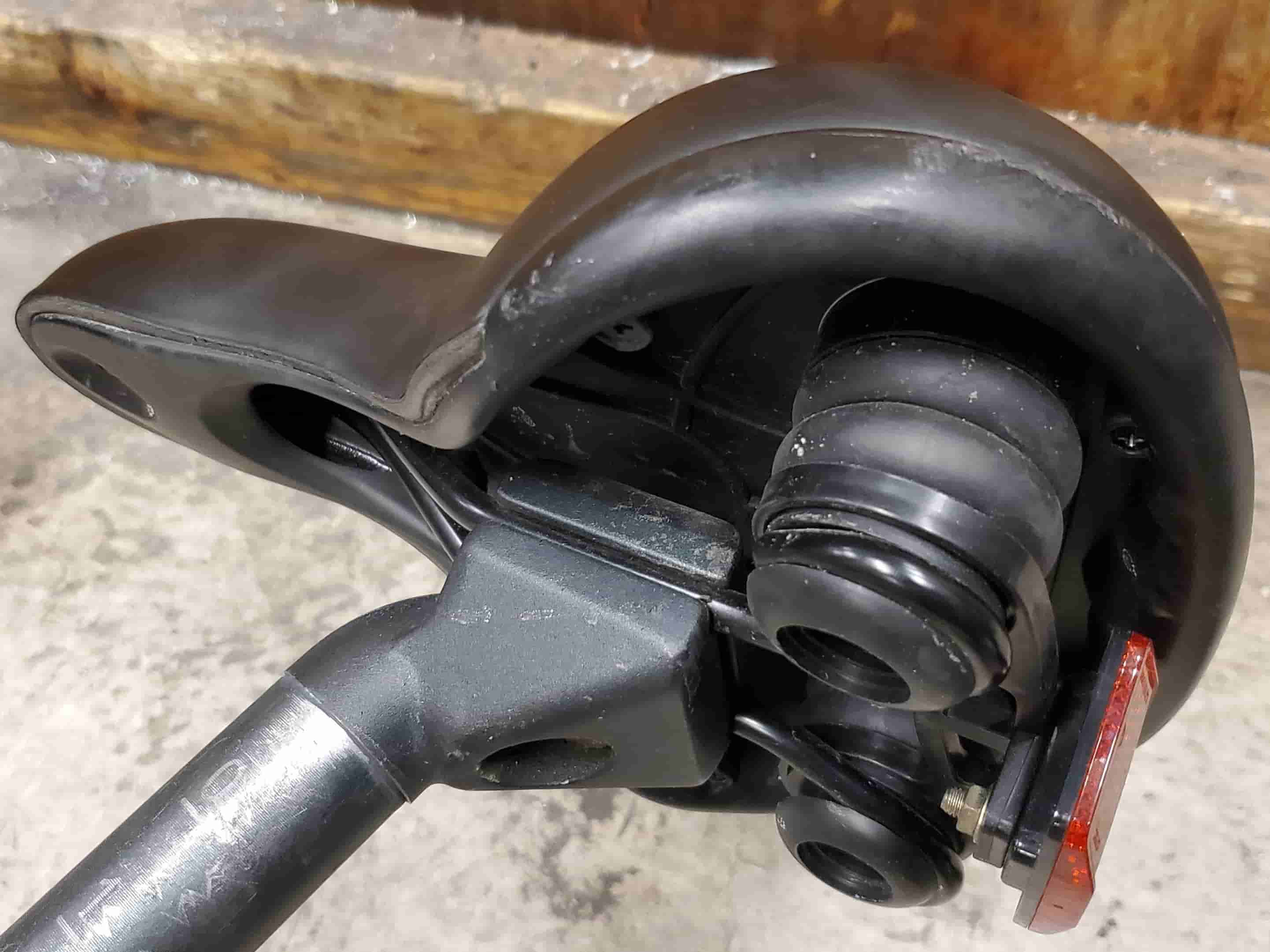
The seat has big cylinders of rubber underneath it to provide shock absorption.
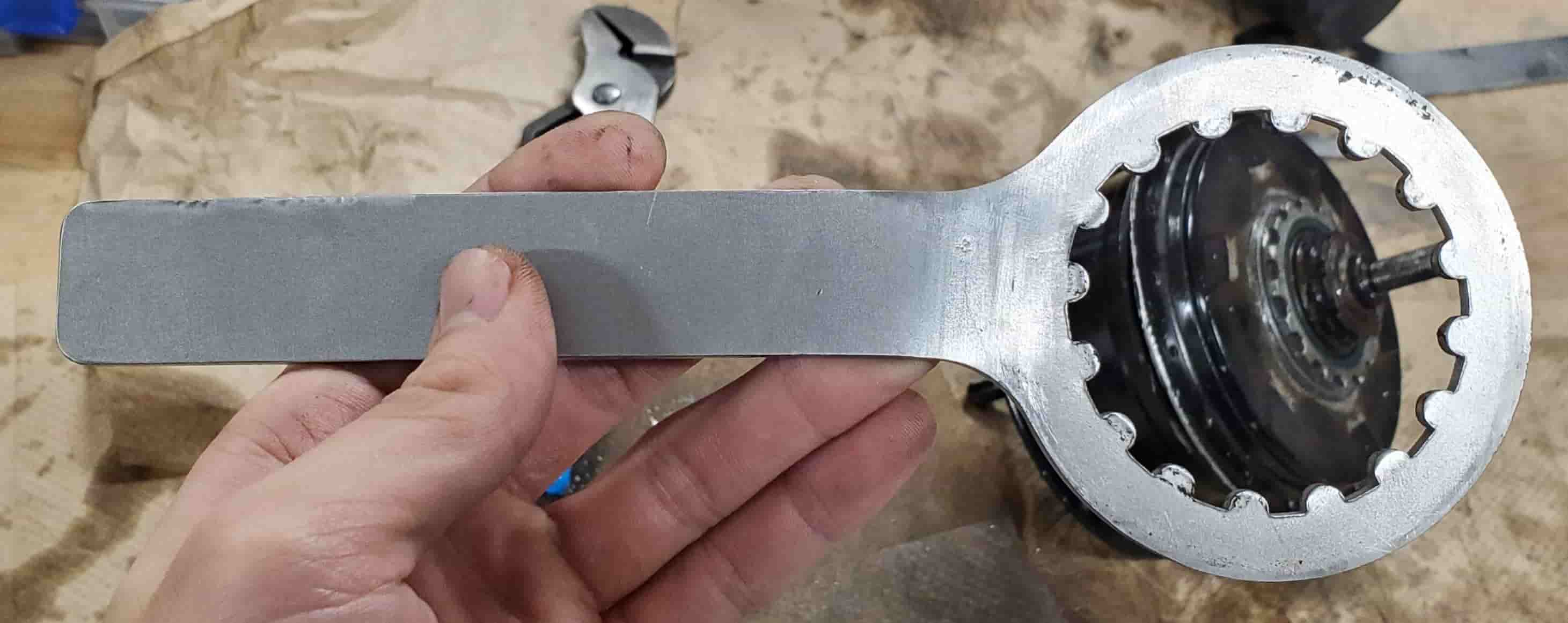
I cut open the back wheel hub (which housed the continuous gear shifter) with a bandsaw because I was not able to disassemble it manually. I had even laser cut a custom wrench out of steel to fit into the splines of the lid, but I bent the wrench trying to open it. I confirmed through the manufacturer’s website and my observations of the opened back wheel hub that the lid screwed onto that part of the hub.